Common Unbound Soil/ Aggregate Tests Used in Transportation Systems
Posted: August 26th, 2021
Student’s Name
Instructor’s Name
Course
Date
Common Unbound Soil/ Aggregate Tests Used in Transportation Systems
k -Westergaard Modulus of Reaction (Plate Bearing)
Plate Bearing Test is used for an in-situ load-bearing test for the solid. The test is done to determinethe bearing capacity of the underneath soil to assess the shape it is likely to take a (Gardiner 107). There are three main objectives for this tests which include estimating the parameters of the design in relation to the bearing capacity of soil, the second one is to confirm the assumed bearing capacity of design stages and the third one is to ascertain the likely foundation settlement under the working load.
The procedure for conducting the test involves loading the steel plate of a random diameter. In this case, the measurements corresponding to the load settlement is recorded as the load continues to be increased (Quintus, Bush, and Baladi 126). During testing, jacking of the steel plate is done against the resistance load. The analytical results depict the final bearing capacity of the soil. However, an allowance safety factor is incorporated to provide safe bearing capacity (Gopalakrishnan et al. 129). Therefore, the test results should contain the following items;
- Raw data,
- The load-settlement curve,
- The recommended allowable pressures
- The yield pressure for the foundation and;
- The modulus subgrade reaction (K|0 for the pavement design.
CBR- California Bearing Ratio
The California Bearing Ratio (CBR) test is a strength test used for comparing bearing material bearing capacity against a well-graded crushed stone. In this case, therefore, a crushed stone material of high quality should present a CBR score of 100%. The primary objective of the test is for evaluating the cohesive strength of the material, consisting of the maximum particle size of not more than 0.75 inches or 19 millimeters (Dawson 312). California Division of Highways developed the test in 1930. Subsequently, numerous states, counties, and the U.S federal agencies adopted it, after which it gradually gained international recognition.
The typical CBR test is done by applying a specific load to a small penetration piston at an estimated rate of 1.3 mm or 0.05 inches per minute. The results are recorded for the total load penetration. The range of the load aggregates is 0.64 mm or 0.025 inches to 7.62 mm or 0.300 inches. The following figure demonstrates a basic CBR example;
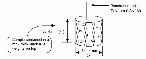
Figure 1: Sample of CBR Test
Once the values in the test are obtained, they are inserted in the following equation to calculate the CBR test results;
Whereby;
X represents material resistance or the load size units as exerted on the piston or pressure for 0.1inches (2.54 mm) or 0.2 inches (5.08 mm) penetration level.
Y is the standard pressure (unit load) for properly graded crushed stones. In this case, 0.1 inches (2.54 mm) penetration is equivalent to 6.9 MPa or 1,000 psi and 0.2 inches (5.08 mm) penetration is equivalent to 10.3 MPa, that is, 1,500 psi.
The following table represents typical values
| General Soil Types | USC Soil Type | CBR Range |
| Coarse-Grained | GP | 30-60 |
| GM | 20-60 | |
| GW | 40-80 | |
| Fine-Grained Soil type | CL LL | 15 or less |
| ML | 15 or less | |
| CH L > 50% | 15 or less |
R Hveem Stabilometer R-value
The R-Hveem Stabilometer R-Value test is used for testing the stiffness of a material. The procedure involves the expression of material resistance on deformation, as a dependent factor for the ratio of transmitted lateral pressure against the applied vertical pressure. The R-value is assigned to the tested materials. R.M. Carmany and F.N. Hveem from California Division of Highways developed the test (Dawson 218). It was first reported in the 1940’s at the time when rutting was the primary concern in wheel tracks. Thus, the test was developed to help improve the CBR test.
Before executing the R-Value tests, the laboratory samples should be fabricated to density and moisture conditions, representing the worst possible in-situ conditions for a compacted subgrade. The R-Value is obtained from the ratio of applied vertical pressure to the developed lateral pressure. Essentially, it measures the resistance of the material against the plastic flow. Stabilometer is the testing apparatus employed in R-Value tests. Figure 2 is a schematic representation of the Stabilometer;
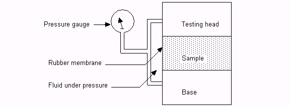
Figure 2: Stabiometer for R-Value Tests
The following equation is used for calculating the R-Value.
Once the measurements are obtained, they are respectively inserted in the equation.
}
Whereby;
R represents the value of resistance
Pv represents the applied vertical pressure, estimated at 160 psi
Ph represents transmitted horizontal pressure at the Pv => 160 psi and,
D represents the Stabilometer fluid displaced just necessary for increasing the horizontal pressure from 5 psi to 100 psi
Mr- Resilient Modulus (Non-Linear)
The resilient modulus (Mr) refers to the underlying material property applied in assessing characteristics of unbound pavement materials. Mainly, the measure is used to measure the stiffness of a material. It provides mean for analyzing the material stiffness based on varied conditions such as stress, density, and moisture level. Mr is also a parameter required for the mechanistic-empirical pavement design method. It is primarily determined using laboratory tests to measure the stiffness of cylinder specimen against a cyclic axial load. Thus, the resilient modulus is a ratio of the applied axle deviation stress and the recoverable strain of the axle. The following equation is used in ascertain Mr.Value;
Whereby;
Jd represents the applied axle deviator stress, and Gr is the recoverable axle strain. Figure 3 below is a graphical display of resilient modulus as defined from repeated load axial tests.
Figure 3: Resilient Modulus Terms
The system components include theloading frame and a crosshead which is mounted with the hydraulic actuator. An actuator is attached with a load cell to help obtain measures of the applied pressure. Equally, the triaxle cell contains the soil sample from which the pressure is applied (Lytton 183). The sample deformation is measured using Linear Variable Differential Transducers (LVDT) set. The results are recorded in the data system, thereby used for calculating resilient modulus through the equation above.
DCP- Dynamic Cone Penetrometer
George F. Sowers first used the Dynamic Cone Penetrometer (DCP) in 1959. The tool uses 6.8 kilograms of steel mass that falls from a 20-inch or 50.8 cm striking an anvil to cause an expected penetration of 3.8 cm (1.5 inches) of diameter cone (Barla, Giovanni, and Barla 109). The cone is positioned at 45 degrees vertex angle seated on the base of the hand-augured hole. The force required to embed the cone to a depth of 1 to ¾ inches is derived from a Standard Penetration Test (SPT) (Lytton 103). Previous uses of the penetrometer have shown that it is useful when augured to depths of about 4.6 to 6.1 meters, that is, 15 to 20 inches. Figure 4 below shows two types of cones, that is, heat treated and zinc plated components.
Figure 4: S-200 DCP
Figure 5 demonstrates the application of the DCP tests
Additionally, the Sleeved Drive Hammer is a designed tool that helps provide a safe approach to performing DCP tests following ASTM STP-399. ASTM STP-399 is the widely accepted portable method used to evaluate the density and strength of soil in situ. The tool is designed such that it fits standard “E” drill rod extensions. It is also compatible with the existing DCP units (Hugo, Frederick, and Martin 119). It is compact, easy to move, and it is zinc-plated to protect it from corrosion. Equally, the tool is capable of disassembling for cleaning and inspection.
NDT Deflection Basin Back Calculation
The test focuses on four significant aspects. These include center load-deflection that shows the total defection of the pavement. This has been utilized over the years for essential input for different overlay design procedures (Barla, Giovanni, and Barla 117). The second aspect is the deflection difference that is close to the load; for instance, the radius of the Curvature, R, Surface Curvature Index (SCI), and the Shape Factor (F1). The parameters usually tend to deflect relative to the stiffness of the upper or unbound regions of the pavement. The third aspect is the defection differences in the basin center measured at about 300 mm to 900 mm (11.8 inches to 35.4 inches) from the pivot point of the load. The fourth aspect is the deflections towards the edge of the basin, which relates reasonably with the subgrade stiffness under the pavement surface.
Works Cited
Barla, Giovanni, and Marco Barla. Prediction, analysis, and design in geomechanical applications: proceedings of the Eleventh International Conference on Computer Methods and Advances in Geomechanics, Torino, Italy, 19-24 June 2005. Bologna: Pàtron Editore, 2005. Print.
Dawson, A. R. Pavements unbound: proceedings of the 6th International Symposium on Pavements Unbound (UNBAR 6), 6-8 July 2004, Nottingham, England. Leiden London: Balkema, 2004. Print.
Gardiner, Mary. Constructing smooth hot mix asphalt (HMA) pavements. West Conshohocken, PA: ASTM, 2003. Print.
Gopalakrishnan, Kasthurirangan, Halil Ceylan, and Nii O. Okine. Intelligent and soft computing in infrastructure systems engineering: recent advances. Berlin: Springer, 2009. Print.
Hugo, Frederick, and Amy E. Martin. Significant findings from full-scale accelerated pavement testing: a synthesis of highway practice. Washington, D.C: Transportation Research Board, 2004. Print.
Lytton, Robert L. Determining asphaltic concrete pavement structural properties by nondestructive testing. Washington, D.C: Transportation Research Board, National Research Council, 1990. Print.
Quintus, H. L., A. J. Bush and Gilbert Y. Baladi. Nondestructive testing of pavements and back-calculation of moduli. Philadelphia, PA: ASTM, 1994. Print.
Expert paper writers are just a few clicks away
Place an order in 3 easy steps. Takes less than 5 mins.